ROV Cable 4×24AWG+2×2×26AWG+1×26AWG+2×1SMF+D-635KG
Underwater Power Cables · Marine & Subsea
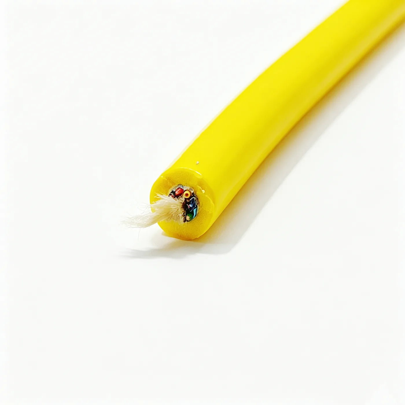
ROV cable 4×24AWG+2×2×26AWG+1×26AWG+2×1SMF+D-635KG
Watertight ROV cable with 4×24AWG power, 2×2×26AWG shielded pairs, 2×1SMF fiber and a 635 kg aramid strength member in an 11±0.5 mm sheath.
Product overview
The ROV cable is a composite watertight cable for subsea vehicle launch and recovery and work systems. A single cable body carries power transmission, control signals, data communication and the tensile load of deployment at the same time. Compared with a conventional subsea cable, its design separates electrical and mechanical duties: the electrical cores only transmit, while the pull generated during launch and recovery is taken by separately arranged strength members, so the cores are not loaded continuously and neither elongate nor break. This model combines power cores, shielded twisted-pair signal cores, a single-mode fiber unit and aramid strength members in one stranded construction. The outer sheath consists of a foam layer and a solid layer, so that the weight of the cable in water approaches the weight of the seawater it displaces; the catenary sag during launch and recovery stays small and the load on the subsea vehicle and the winch is reduced.
Construction and materials
Conductor: stranded copper strands, 24AWG (0.2 mm²)
Insulation: PE
Outer sheath: TPU, 2.4+0.6 mm thick, yellow
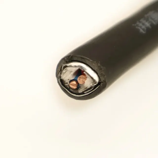
The power group consists of four insulated single cores with polyethylene insulation, distinguished by black, red, yellow and green so that both cable ends can be terminated in the correct position and faults can be traced on site. The signal group consists of two twisted pairs and one separate single core, all at 26AWG nominal cross-section; the twisted pairs suppress crosstalk between pairs and the separate core can serve as a spare or carry a dedicated control signal, with actual use defined by the connectors at each end. A single-mode fiber unit is cabled in as well for long-distance data return. The fiber unit is left with a suitable excess length during cabling so that it is not the first element to take load when the cable is tensioned, which protects the fiber core from damage.
Aramid yarn is cabled together with the electrical cores and forms the main load-bearing element of the whole cable, with a nominal capacity in the 635 kg class. The core is stranded in a left-hand lay with the stranded diameter held within 4.5±0.5 mm; the lay parameters are matched to the diameter of each element so that the core is round, the load is evenly distributed between elements and the assembly does not open up after cabling. A longitudinal aluminum foil shield is applied over the core with the metal side facing in, together with one 7/0.15 tinned copper drain wire that provides a continuous low-resistance discharge path for the shield. A 16-spindle braid in an 8+8 configuration is applied over the shield with a coverage of approximately 50%, balancing shield continuity against cable flexibility.
The outer sheath is extruded in thermoplastic polyurethane, with a foam inner layer and a solid outer layer, and the finished outer diameter is held at 11±0.5 mm. The foam layer lowers the specific gravity of the whole cable so that it approaches neutral buoyancy in water; the solid outer layer provides continuous protection against abrasion, hydrolysis and seawater corrosion. The sheath is mainly yellow, with a natural finish also available, and can be adjusted to project requirements.
Key features
- Composite transmission: one cable body carries power, control signals, data fiber and strength members, reducing the number of connections between subsea devices.
- Separated load path: the strength members are arranged independently, so launch and recovery tension does not act directly on the electrical cores and the fiber unit.
- Near-neutral buoyancy: the combined foam and solid sheath lowers specific gravity while maintaining mechanical protection, improving underwater attitude and handling.
- Complete shielding: longitudinal aluminum foil, drain wire and braid work together to form multiple shielding and protection layers that reduce the effect of external interference.
- Flexible and bend-resistant: stranded conductors and the cabling construction give good bending performance for repeated launch and recovery over winches and cable guides.
- Easy to customize: core combinations, sheath color, finished outer diameter and delivery length can all be adjusted to project requirements.
Electrical and mechanical performance
Electrical and mechanical performance varies with the operating conditions and with the connectors at both ends. Insulation resistance, withstand voltage, shielding effectiveness, tensile and bending strength, abrasion resistance and hydrolysis resistance must be determined together with working depth, launch and recovery frequency and the mating connectors; the final values are stated in the specification document confirmed by both parties. Because the fiber unit, signal pairs and power cores are independent of each other, the electrical parameters of each group should be confirmed separately rather than represented by an overall figure for the cable. For long-term service in seawater, the hydrolysis resistance of the sheath and the continuity of the shield deserve particular attention, and sealing and strain relief at both cable ends are recommended.
Typical applications
The cable is intended for subsea vehicle systems, subsea work tools and subsea observation equipment, carrying deck power, control commands and sensor data in one cable body while the strength members handle deployment and recovery. It also suits subsea camera and lighting systems, subsea manipulators, inspection and survey equipment, and other cases where a power and data link is required between surface and subsea equipment. At greater working depth or in strong current, the near-neutral buoyancy sheath helps reduce sag and the risk of entanglement; where frequent launch and recovery is required, the combination of stranded conductors and braid helps extend service life. If clamps or buoyancy modules are to be added to the cable, this should be stated in advance so that the shield and sheath are not damaged during installation.
Selection and customization
Selection should start with the number and cross-section of the power cores, the number of signal pairs required, whether a fiber unit is included, and the launch and recovery method together with the required load rating; the sheath type and finished outer diameter follow from these. Where oil, chemical media or continuous immersion are present, this should be stated so that the sheath construction and the end sealing method can be confirmed. Color coding, length and end preparation can be agreed at order; connectors and sealing arrangements differ considerably between projects and should be defined in the specification document, which remains the final basis.
Related in Underwater Power Cables
 Custom
 Custom
 Custom
 Custom
Engineering enquiry