ROV Cable 4×24AWG + 2×2×26AWG + 1×26AWG + D-635KG, Power and Signal
Underwater Power Cables · Marine & Subsea
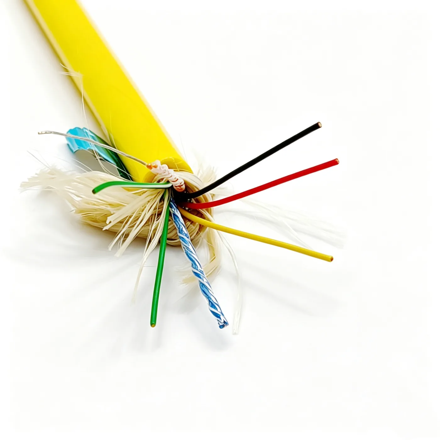
ROV cable 4×24AWG+2×2×26AWG+1×26AWG+D-635KG
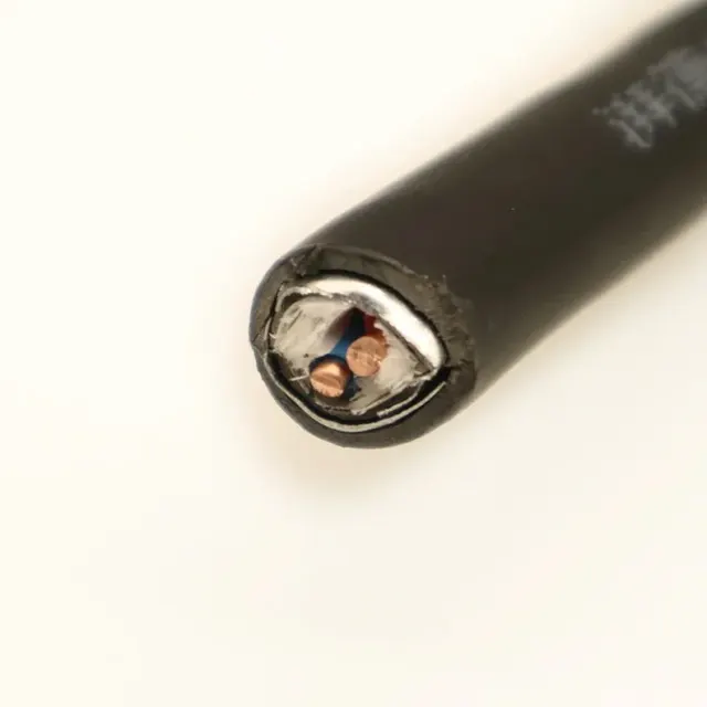
ROV cable with four 24AWG power cores and 26AWG signal pairs in one body, PE insulation, foil and braid shielding, foamed TPU double sheath, 10.6mm OD.
Product overview
The ROV cable is a multi-core composite cable designed for underwater vehicles and subsea working equipment. It carries power and signal circuits within one cable body, which reduces the number of external cables on the equipment and simplifies deployment and routine maintenance. The cable suits continuous or intermittent immersion, typically for ROV umbilicals, subsea lighting and camera power, and sensor data return. Compared with land-based cables it faces hydrostatic pressure, hydrolysis, towing abrasion and repeated bending at the same time, so the design emphasises sheath sealing and wear resistance, shield continuity, and a balance between cable weight and flexibility.
The cable is built on stranded copper conductors with polyethylene (PE) insulation, aluminium foil shielding and a tinned drain wire, plus a metallic braid. A foamed thermoplastic polyurethane (TPU) inner layer and a TPU outer layer form a double-sheath construction that combines hydrolysis resistance, abrasion resistance and low-temperature flexibility. Power cores and signal units are cabled into a single core, and each circuit uses a different insulation colour for identification and wiring checks on site. Performance figures and acceptance criteria are as stated in the specification document confirmed by both parties.
Construction and materials
- Power cores: four stranded copper conductors of 24AWG, nominal cross-section 0.2mm² per core, PE insulation in black, red, yellow and green for circuit identification and wiring checks.
- Signal units: two 26AWG signal pairs plus one single core of the same size, used for control commands and status feedback.
- Conductor stranding: copper wires are stranded in a left-hand lay, which distributes stress more evenly in bending and improves flexibility for equipment that is deployed and recovered frequently.
- Shielding and drain: aluminium foil is applied during cabling with the metal side facing inwards, together with one 7/0.15 tinned wire as a drain that provides the shield with a continuous discharge path.
- Braid: 8+8 construction, 16 carriers in total, coverage approximately 50%, giving the core mechanical protection and improving shield continuity.
- Inner sheath: foamed TPU layer that reduces cable weight while providing cushioning and a round support.
- Outer sheath: extruded TPU, yellow combined with natural colour; finished outer diameter 10.6±0.5mm.
Construction parameters at a glance
The conductor size and cross-section, insulation material and colours, shielding and drain arrangement, braid construction and coverage, inner and outer sheath materials and finished outer diameter of this type are listed item by item in the Construction and materials section above and are not repeated here, so that the same parameters do not recur through the text. If a specification summary in datasheet form is required for a project, it can be issued separately on request, subject to the specification document confirmed by both parties.
Key features
- Integrated power and signal: power cores, signal pairs and the single core share one cable, so subsea equipment can be powered and communicate over a single line.
- Dual shielding: aluminium foil with a drain wire forms the primary shield, and the outer metallic braid further suppresses electromagnetic interference for stable signal transmission.
- Foamed inner layer for weight reduction: the foamed layer lowers weight per unit length while keeping the cable round, reducing load and deployment drag on underwater equipment.
- TPU outer sheath: the thermoplastic polyurethane sheath resists abrasion and hydrolysis and stays flexible at low temperature, which suits repeated bending and towing during operation.
- Compact construction: a small outer diameter is maintained while several circuits are integrated, which eases bulkhead passage, sheave routing and spooling.
- Easy circuit identification: different insulation colours make circuits easy to distinguish and terminate, reducing the risk of wiring errors on site.
Electrical and mechanical performance
- Longitudinal tensile strength is designed for 635KG. The permissible pull also depends on the launch and recovery mechanism, the drum diameter and the working depth, and should be defined at the selection stage.
- Electrical values such as insulation resistance, withstand voltage and conductor DC resistance depend on the conductor construction and materials selected, and are as stated in the specification document confirmed by both parties.
- The operating voltage class and minimum bending radius must be determined together with the sheave diameter of the handling system, the drum diameter and the working depth, so that installation and recovery stay within the limits of the cable.
- The combination of sheath and foamed layer gives the cable mechanical margin under repeated bending and towing abrasion; actual values are subject to the specification document and sample test results.
- Watertight performance under long-term immersion is achieved jointly by conductor stranding, shield coverage and the double-sheath design, and must match the termination method actually used.
Typical applications
- ROV umbilicals and tethers: power for the vehicle, thrusters and lighting, with control and video signals returned on the same cable.
- Subsea camera and lighting systems: one cable carries both power and image signals, reducing the number of subsea connectors and joints.
- Subsea sensor nodes: power and data collection for pressure, temperature and attitude sensors, suited to observation systems deployed over long distances.
- Subsea tooling: manipulators, lamp arrays, camera pan-and-tilt units and other equipment that needs combined power and signal transmission.
Selection and customisation notes
- Power core cross-section, core count and the number of signal pairs can be combined to suit the power demand and signal type of the equipment; fibre or coaxial units can be integrated into the construction when required.
- Sheath colour, print legend and overall dimensions can be adjusted to project requirements.
- Finished length, end preparation and connector type should be defined before ordering; delivery condition is as stated in the specification document confirmed by both parties.
- For greater working depth, frequent deployment or strong electromagnetic interference, describe the operating conditions at the selection stage so that shielding and sheath configuration can be designed accordingly.
- For long-term immersion, terminations and ends should be processed to match the shield and sheath construction of the cable, so that poor end sealing does not shorten the overall service life.
Related in Underwater Power Cables
 Custom
 Custom
 Custom
 Custom
Engineering enquiry