PDK21301 3×70 mm² + 3×16 mm² Crane and Hoist Drum Cable, 0.6/1 kV, 41 mm
Crane & Hoist Drum Cables · Industrial Automation
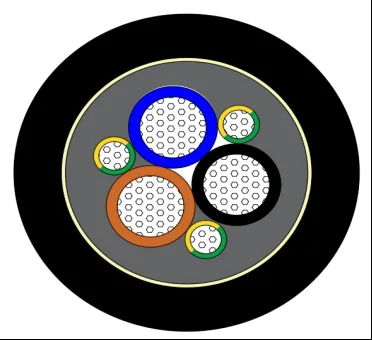
PDK21301
PDK21301 drum cable with 3×70 mm² power and 3×16 mm² auxiliary cores, PVC insulation, NBR inner and TPU outer sheath, 41 mm OD, rated 0.6/1 kV.
Product overview
Drum cable is wound and paid out repeatedly with the reeling action of the equipment drum and is a key component in the travelling power supply of cranes, overhead travelling cranes, spreaders and various handling machines. During winding the cable is subjected both to bending and to dragging and tension, so a balance must be struck between flexibility, tensile strength and sheath abrasion resistance. The PAIDE Cable PDK21301-3×70+3×16 drum cable combines three large-section power cores and three auxiliary cores in one cable body, for power circuits with high current-carrying requirements that are repeatedly deployed. Conductor stranding, insulation arrangement, double sheath and tensile reinforcement are all designed for drum duty: the power cores carry current, the auxiliary cores serve control and earthing, and all cores are cabled in the same direction so that stress in the core is more even.
Drum duty tests the cable in two directions: repeated bending from winding and paying out, and longitudinal dragging from the rise and fall of the spreader and the travel of the machine. The first tests the conductor stranding and sheath flexibility, the second the mechanical strength of the reinforcement and sheath. Only when both are matched can the cable remain stable through long-term reciprocating motion. The dimensional parameters of this specification are listed in the construction and materials section below, and the rated voltage, conductor resistance, temperature range and bending radius in the electrical performance section, so that they can be taken together at selection.
Construction and materials
For the conductors, both power and auxiliary cores use high-purity bare copper, produced by stranding a number of fine wires. The power core has a cross-section of 70 mm², stranded from 1428 copper wires of 0.25 mm diameter, with a stranded conductor diameter of approximately 12.4 mm; the auxiliary core has a cross-section of 16 mm², stranded from 560 copper wires of 0.19 mm diameter, with a stranded conductor diameter of approximately 5.2 mm. Fine-wire stranding keeps the conductor supple, and the slip between individual wires under bending distributes stress, which helps reduce fatigue damage from repeated flexing and extends cable life under drum duty; the regular stranded diameter also helps apply the insulation layer to an even thickness.
For insulation, every core is PVC insulated. Power core insulation has an average thickness of 2.0 mm and a minimum thickness of not less than 1.7 mm; auxiliary core insulation has an average thickness of 1.0 mm and a minimum thickness of not less than 0.85 mm. Insulation colours such as blue, brown and black distinguish the phases, with a yellow-green earth core provided as required, which eases on-site connection and fault tracing. The insulation separates the phases and provides withstand voltage; its thickness control directly affects the long-term electrical safety and mechanical flexibility of the cable.
The sheath system is a double-layer construction with an inner and an outer sheath. After cabling, an NBR inner sheath is extruded over the cores, average thickness 1.2 mm, black, giving a cable diameter of approximately 35 mm after the inner sheath. NBR has good oil resistance and protects the insulated cores in machinery where oil mist and oil contamination are present, reducing attack on the insulation. Outside the inner sheath there is a Kevlar braid layer with a braiding ratio of approximately 50%, which carries the axial tension generated during winding and restrains relative movement between sheath and cores, keeping the cable structurally stable through deployment.
The outermost layer is a TPU outer sheath with an average thickness of 3.0 mm and a minimum thickness of not less than 2.55 mm, black. The TPU sheath is abrasion resistant, cut resistant and weather resistant, and withstands repeated scraping against the drum surface, guide sheaves and the ground; even with slight surface scuffing the sheath remains continuous and the internal structure is not exposed. The final finished outer diameter is 41±1.0 mm.
Key characteristics
- Wide temperature range: the sheath material remains flexible at low temperatures and does not soften or deform under the temperature rise of operation, covering both cold outdoor starting and continuous duty;
- Good bending capability: the permissible bending radius is small, so the cable follows the winding path on the drum and repeated deployment causes less damage to conductors and sheath;
- Oil-resistant protection: the NBR inner sheath suits machine shops with oil contamination and oil mist, reducing the risk of sheath swelling and cracking;
- Tensile reinforcement: the Kevlar braid layer increases the tensile capacity of the cable and prevents internal movement during deployment;
- Abrasion and scrape resistance: the TPU outer sheath suits direct contact with drums, sheaves and the ground and resists wear-through in long service;
- Flexible and durable: fine-wire stranded conductors with a double sheath give a longer overall mechanical life under repeated flexing.
Electrical performance
The rated voltage of this specification is 0.6/1 kV, allowing use in low-voltage power circuits. The maximum DC conductor resistance at 20 °C given in the specification is 0.272 Ω/km for the power cores and 1.21 Ω/km for the auxiliary cores. These values are maximum permissible limits and can be used directly when calculating line voltage drop and current-carrying capacity, so that design margin is preserved.
Besides the electrical figures above, the mechanical service conditions for this model are: rated temperature range -40 °C to +90 °C and minimum bending radius 10 times the cable outer diameter. The lower temperature limit determines whether the cable can be deployed normally outdoors in cold conditions, while the upper limit corresponds to the ambient temperature rise during operation; the bending radius must match the drum diameter, sheave size and deployment speed, and should be confirmed against the actual winding space on site to avoid prolonged bending below the specified radius.
It should be noted that current-carrying capacity is not a single fixed figure but depends on installation method, ambient temperature, number of wound layers and the number of cores working at the same time. On drum equipment, multi-layer winding worsens heat dissipation, so a margin should be allowed for the actual number of layers, and the working current confirmed against the on-site conditions where necessary.
Related constructions in the series
The PAIDE drum and crane cable series includes several model families such as PDK21301 and PDK21303, covering different core counts, cross-sections and composite constructions. Besides this power drum cable, the following constructions are common in the series:
- Multi-core signal deployment type, 48×2.5 mm² construction, rated voltage 300/500 V, temperature range as the main specification, reinforced at the centre with a 3 mm diameter steel wire rope under a PVC covering, NBR inner sheath and TPU outer sheath, finished outer diameter approximately 47 mm, suited to drum applications with a large number of control and signal lines;
- Heavy-duty composite type, 45-core construction of 9×4 mm²+28×1.5 mm²+8×1.0 mm², rated voltage 450/750 V, temperature range -30 °C to +105 °C, Kevlar braid reinforcement able to withstand 1000 kg of pull, thick-wall PUR outer sheath, finished outer diameter approximately 57.5 mm, often used on spreaders and other heavy-duty deployment equipment;
- Compact small-section type, 3×4 mm²+1×2.5 mm² construction, rated voltage as the main specification, temperature range -40 °C to +105 °C, polyether polyurethane outer sheath, finished outer diameter approximately 13.8 mm, suited to equipment with limited installation space;
- Fibre composite type, 3×35 mm²+3×35/3+20×2.5 mm² construction with 24 single-mode fibres, rated voltage 6/10 kV, overall tensile strength 2000 N, temperature range as the previous construction, allowing remote communication and condition monitoring alongside power transmission.
These constructions address different priorities: where many signal cores are needed the multi-core deployment type is preferred, for heavy-duty applications such as spreaders the composite heavy-duty type, where installation space is tight the compact type, and where data must be returned at the same time the fibre composite type. Once the core count and cross-section combination is fixed, the sheath material and reinforcement method are determined against the temperature range, tensile requirement and installation environment.
Applications and customisation notes
This drum cable series is typically used in the power winding circuits of cranes, overhead travelling cranes and spreaders, in the travelling power supply of handling machines, and in industrial equipment requiring repeated winding and dragging. By default the sheath is printed with the company name, model, production date and metre marking, which assists on-site identification, cutting and traceability.
Drum cable is a product with a high degree of customisation to the duty. The parameters in this article are based on the specification of this drum cable; if the actual conditions impose special requirements on the lower temperature limit, bending radius, tensile load, sheath material or core and cross-section combination, PAIDE Cable can be contacted to define a construction based on the specific drum diameter, deployment speed and operating environment; model parameters not listed here are provided from the corresponding specification. At purchase it is advisable to state the rated voltage, core count and cross-section, drum diameter, deployment frequency and whether oil or water is present, so that a suitable reinforcement and sheath material can be matched and the cable runs reliably under long-term winding duty.
In addition, drum diameter and deployment speed directly affect the number of bending cycles and the friction intensity; on installation the exit angle between the guide sheave and the drum should be as straight as possible so that the cable does not cross and stack between layers. For equipment used outdoors, the effect of UV, rain and temperature variation on the sheath should also be considered, and the operating environment can be stated at the selection stage so that the supplier configures the sheath material and reinforcement accordingly. In routine maintenance the sheath surface should be checked periodically for deep scores, bulges or hardening, and the cable replaced promptly if anything abnormal is found, so that damage to the internal structure does not affect operation of the machine.
Related in Crane & Hoist Drum Cables
Engineering enquiry