Spring Cable 4×13AWG + 3×24AWG, Coiled, 1200 mm
Spiral & Spring Cables · Industrial Automation
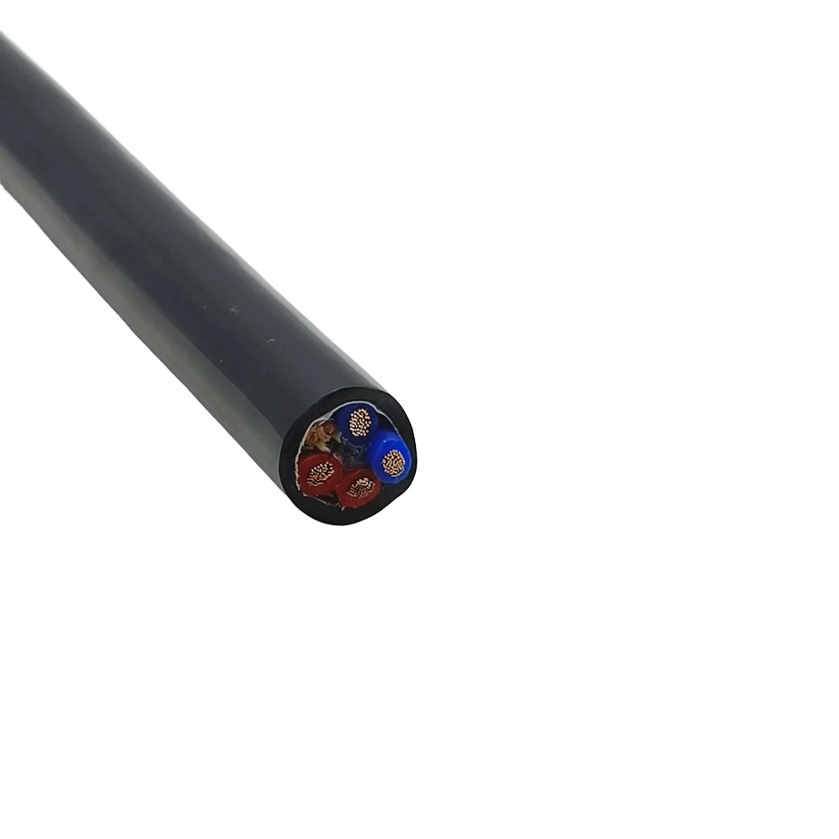
Spring cable 4×13AWG + 3×24AWG
Coiled spring cable with 4 × 13AWG power cores and 3 × 24AWG signal cores, foil and tinned braid shield, 1.5 mm TPU sheath, 12 mm finished diameter.
Product overview
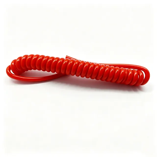
Spring cable, also called spiral or coiled cable, is a cable of special construction in which the finished cable is wound into a helix with straight sections left at both ends. It relies on the cable's own elastic memory to pay out and retract, so that cable is taken up automatically where equipment moves back and forth, doors open and close, instruments are raised and lowered, or a handset is pulled; this keeps cable off the floor, prevents tangling and avoids damage from being pulled hard, and keeps the wiring tidy within a limited travel.
This type is 4×13AWG + 3×24AWG, combining larger power cores with smaller signal cores in one cable so that supply and control signals are carried together. This reduces the number of harnesses on the equipment and suits machines and instruments with limited installation space that move back and forth continuously.
Construction
This type is built in the sequence conductor stranding, insulation extrusion, cabling with tensile elements and fillers, shielding, sheath extrusion and helix forming, with each layer having a defined function. The main dimensions and material configuration are listed in this section; the following sections describe them qualitatively only.
- Conductors and insulation: copper multi-strand conductors, stranded separately for power and signal cores in a left-hand direction; cores are colour-coded to simplify connection and maintenance.
- Cabling: cores stranded in a left-hand direction to a core diameter of about 8.9 mm; the stranded construction is tight and stable, so relative movement between cores in repeated bending is small.
- Tensile elements and fillers: 3 aramid fibre elements are placed in the core as the load-bearing unit, together with 10 fibre fillers and polypropylene filler yarns, giving a round section and even load distribution; in tension the load-bearing elements take the strain, reducing the risk of the conductor being drawn thinner.
- Shielding: a composite shield of aluminium foil plus tinned wire braid with 75% coverage suppresses interference from the supply circuit and keeps signal transmission stable.
- Tape and sheath: non-woven tape is wrapped over the core and the outer sheath is black TPU applied by extrusion, 1.5 mm thick, for a finished diameter of 12 ± 0.3 mm. TPU combines the abrasion resistance of plastics with the elasticity of rubber, performs well in oil, low temperature and weathering, and suits repeated extension duty.
- Helix forming: the cable is wound into a helix with a free spring length of 1200 mm and a spring outer diameter of 48 ± 0.5 mm; straight sections are left at both ends, 5.5 m in length, running parallel to the spring axis to simplify fixing and termination.
Key features
- Extension and retraction: the coiled section extends beyond its free length and returns to the coiled state when the force is released, reducing manual cable handling and tidying.
- Mixed cross-sections: larger power cores carry the supply and smaller signal cores carry signals and control, so one cable does both jobs with simple connection and little space.
- Interference suppression: the combination of tinned wire braid and aluminium foil suppresses electromagnetic interference; the braid is easy to earth and solder, and the tinned layer resists oxidation for stable termination.
- Tensile protection: aramid strength elements work with the filler structure to reduce the risk of conductor damage from tension and repeated bending.
- Sheath performance: the TPU sheath is abrasion-resistant, oil-resistant and flexible, and remains pliable at low temperature.
- Stable shape: the cabled construction and filler design keep the section round, so the helix is uniform after forming and retraction is consistent.
- Customisable dimensions: the ratio of coiled section, straight sections and overall length can be adjusted to equipment travel and installation space.
Main parameters
The specification of this type is given in the product overview, the constructional dimensions and materials are listed under Construction, and electrical and mechanical performance is described in the following section; the same parameters are not repeated here.
Rated voltage, temperature rating, conductor DC resistance, minimum bending radius and flex life vary with the duty and the construction combination and can be confirmed to project requirements; items not listed are subject to the specification document confirmed by both parties.
Electrical and mechanical performance
A single cable carries both a power circuit and a signal control circuit, so insulation and shielding between cores directly affect performance. The aluminium foil provides an overall shield while the tinned braid both reinforces shielding and provides earthing and drain paths; with the cabling and fillers properly controlled, coupling from the power cores into the signal cores is reduced and signal transmission stays stable. The insulation between power and signal circuits is complete, preventing crosstalk between the two, and with proper termination at both ends the control signal is more reliably stable throughout repeated movement.
Mechanically, extension of the coiled section depends on uniform deformation of the structure, and consistency of sheath thickness and diameter directly affects retraction stability. The straight sections run parallel to the spring axis so that load at the terminations acts in one direction, reducing stress concentration near the fittings; the aramid elements carry the main tension so that the conductors stay within a safe load range when the cable is pulled straight. During repeated extension and retraction, the cabled construction and fillers together maintain the section shape and prevent the cores from shifting along the helix.
Typical applications
- Automation equipment and industrial robots: power and signal connection for end effectors, moving slides and fixtures.
- Medical and test instruments: cables for probes, control handles and moving parts.
- Doors and access equipment: automatic doors, barriers and rising bollards, where cable must be taken up as the unit opens and closes.
- Vehicles and construction machinery: joints that extend and retract frequently.
- Stage, audio and mobile lighting: power and signal cable for equipment that is raised, lowered or moved.
- Other retractable connections: portable instruments, controller handles and handheld terminals.
Selection and customisation notes
- Core and cross-section combination: set the cross-sections and number of power and signal cores from the load and the number of signal circuits; shielded and unshielded cores can also be mixed.
- Shielding: choose aluminium foil, tinned wire braid or a combination according to the electromagnetic environment, and specify braid coverage where required.
- Sheath material and colour: can be adjusted to the service environment and appearance requirements.
- Dimensions: spring outer diameter, free length, straight section length and overall length can all be customised to the installation space; the straight sections can be specified parallel to the spring axis or brought out at a particular angle.
- Termination: connectors, terminals or moulded joints can be fitted to drawing, with suitable tensile treatment at the ends.
- Environmental suitability: for low temperature, oil contamination, UV, salt spray or frequent flexing, state the sheath material and construction requirements explicitly in the specification document; PAIDE Cables manufactures to the confirmed document.
To confirm parameters or select a type, please contact the PAIDE Cables technical team; the specification document confirmed by both parties is the final basis.
Related in Spiral & Spring Cables
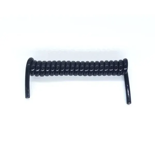 Custom
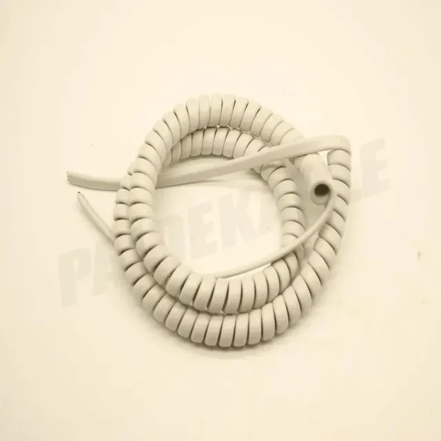 On request
 PDK71902
 Spring cable 2x3.2
Engineering enquiry