PDK81301-4×1.0mm²+STP CAT6 Watertight Optoelectric Cable
Watertight Optoelectric Cables · Marine & Subsea
PDK81301
Watertight optoelectric cable with four 1.0 mm² power cores and a shielded STP CAT6 pair, tinned copper, 10D bending radius, 4000 N tensile.
Product overview
The watertight optoelectric cable is a class of specialty cable designed for long-term subsea working environments. It concentrates power transmission, signal control and data communication in one cable body, reducing the number of penetrations and connection points required by subsea equipment. PDK81301-4×1.0mm²+STP CAT6 is a typical specification in the PAIDE Cable subsea and watertight cable family: four power cores plus one individually shielded network pair, intended for subsea equipment that needs power supply and high-speed data return at the same time.
A subsea environment places very different demands on a cable than a land installation. Water pressure, long-term immersion, reciprocating towing and coiling all act continuously on the cable, so the design focus is not only on electrical values but also on the compactness of the construction, the hydrolysis resistance of the sheath and the stability of the shield under wet conditions. This specification uses a fairly complete construction on all three counts: the conductor is tinned to suppress oxidation, the network pair is individually shielded to protect signal quality, fillers keep the core round, and the outer sheath is made of a hydrolysis-resistant material. Layer dimensions are listed in the construction section, the electrical and optical values in the electrical and fiber performance section, and the bending radius and temperature conditions in the mechanical and environmental characteristics section.
Construction
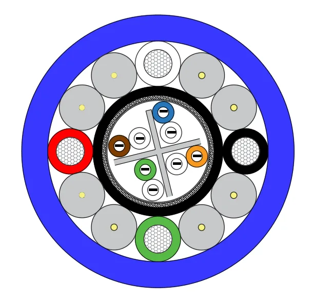
From the inside out the cable comprises conductor, insulation, network group shield, inner sheath, fillers and strength layer, and outer sheath; the power cores and the network pair are cabled in the same direction so that the assembly stays round and compact.
The conductor is tinned copper. The power cores have a cross-section of 1.0 mm² in a stranded construction with a stranded diameter of about 1.3 mm; the single cores used in the network group have a cross-section of 0.2 mm² in a stranded construction with a stranded diameter of about 0.61 mm. The tin coating isolates the copper from moisture and lowers the risk of conductor oxidation under long-term immersion, which matters particularly for equipment that is repeatedly submerged or kept in water for long periods; tinning also makes the conductor easier to solder and crimp.
Two insulation materials are used. The power cores have PP insulation with an average thickness of 0.4 mm, a minimum thickness of 0.34 mm and an insulation diameter of 2.1 mm; the core colors are black, white, red and green for phase identification on site. The network group has FEP insulation with an average thickness of 0.2 mm, a minimum thickness of 0.17 mm and an insulation diameter of 1.0 mm, covered by a composite shield of aluminum foil plus tinned copper braid at approximately 80% coverage. FEP has a low dielectric constant and stable temperature behavior, which helps maintain transmission consistency of the high-speed data pair; the foil and braid combination balances shielding effectiveness at high frequency against mechanical flexibility.
A black PE inner sheath is extruded over the network group with the same average thickness as the power core insulation and a minimum thickness of 0.35 mm; the finished diameter of this layer is about 6.0±0.2 mm. The inner sheath separates the network group from the power cores structurally and provides mechanical protection for the shield, reducing the chance of the shield being stretched or damaged during cabling.
The filler and strength layer consists of 8 PP filler rods, including 1500D LCP fiber. The filler rods keep the core round and compact after cabling and reduce the chance of core displacement under subsea pressure; the LCP fiber takes the longitudinal tensile load, so the tension of towing and launch and recovery is carried mainly by the strength member rather than transmitted to the conductors, protecting the long-term reliability of the conductors and the fiber unit.
The outer sheath is TPU in dark blue with an average thickness of 1.2 mm and a minimum thickness of 1.02 mm; the finished outer diameter is about 12.6±0.3 mm. TPU offers a good balance of hydrolysis resistance, abrasion resistance and flexibility and is a common choice for subsea cable sheaths; the dark blue jacket is also easy to identify and locate in water.
Electrical and fiber performance
The rated voltage of this specification is 300/500 V. Maximum DC conductor resistance at 20 ℃ is 18.7 Ω/km for the power cores and 84.1 Ω/km for the single network cores. The network pair is an STP CAT6 construction and, with the braided shield, meets the Ethernet data transmission needs common in subsea equipment. The resistance of the two core types differs considerably, so voltage drop should be calculated separately for each circuit and the network cores should not be used for power supply.
Products in the same family can also be fitted with a fiber unit. PDK81301-6core Single-mode Fiber, for example, uses G657A2 single-mode fiber with 6 cores, aramid yarn as strength member and a PUR outer sheath; the finished outer diameter is about 5.5±0.5 mm and attenuation is no more than 0.3 dB/km at 1550 nm and no more than 0.5 dB/km at 1310 nm. Subsea equipment that needs long-distance, high-bandwidth return usually adds such a fiber unit alongside the power and network cores to form an optoelectric construction; with the fiber and electrical units in one cable, a single penetration and sealing arrangement is enough for both power and data, so the number of penetrations and the number of potential leak points fall.
Mechanical and environmental characteristics
The minimum bending radius is 10D (D being the cable outer diameter) and the rated temperature is -40℃~+105℃. The low bending radius allows use with smaller drum diameters and in compact routing spaces, while the wide temperature range covers both surface operation and low deep-water temperatures. Minimum thickness values are also specified for the sheath to limit eccentricity and ensure the sealing performance of the cable under water pressure; conductor and insulation dimensions are likewise designed to eccentricity control requirements, so that no local weak points form when the core is under pressure.
Other specifications in the family vary in parameters with conductor cross-section and application. 81301-4×2.5mm², for example, uses a stranded construction and PP insulation with a TPU outer sheath, a finished outer diameter of about 11.6±0.3 mm, a rated voltage of 1000 V and a DC conductor resistance of about 7.45 Ω/km (same test conditions as above), with the same minimum bending radius and temperature range as the main specification; PDK81301-1×2.0mm² is a 113/0.15 construction with PE insulation, an XLPE inner sheath and a TPU outer sheath, a finished outer diameter of about 16±0.3 mm and a minimum bending radius of 15D. Products with tensile requirements, such as PDK81604-2×16AWG+23AWG+ADS 1×2×23AWG-400KG, add water-blocking yarn and 3000D LCP fiber, use the same LCP fiber specification for the braid as in the filler rods, and have a foamed TPU inner sheath and a finished outer diameter of about 14±0.5 mm with a tensile strength of up to 4000 N, making them suitable for launch and recovery equipment subject to higher tension.
Typical applications
These cables are mainly intended for equipment connections that are permanently or repeatedly exposed to water: power and data links between a subsea vehicle and its surface control unit, power and signal connections for subsea camera and lighting assemblies, power supply and data return for subsea sensor arrays, and marine and offshore engineering applications that require a hydrolysis-resistant sheath. Where equipment must be powered, carry control signals and return video or network data at the same time, the optoelectric construction clearly reduces the number of penetrations and therefore the number of potential leak points.
Maintenance costs for subsea equipment are usually higher than for surface equipment, and a single dive often has to make power, control and data connections at once, so cable reliability directly affects the efficiency of the whole operation. Selecting a composite cable with a compact construction, complete shielding and a hydrolysis-resistant sheath, and ensuring that the bending radius and fixing method meet requirements during installation, can effectively reduce unexpected interruptions during subsea work.
Customization and selection
Four conditions should be established first at selection: working depth and whether immersion is continuous, supply voltage and current demand, data interface type and rate, and whether installation is fixed or involves frequent launch and recovery. These four conditions largely determine conductor cross-section, core combination, shield type and strength member configuration.
On this basis the PDK81301 series offers various core combinations, such as 2×0.6+2×2×0.15, 2×1.5, 4×0.5, 2×4+2×2×0.5 and 3×2.5+8SMF; the network group can use twisted-pair constructions with different shielding, such as UTP CAT5E, with the cable category set by the data rate requirement; tensile ratings can be configured as needed, commonly 50KG, 250KG and 600KG; and the fiber unit can be single-mode or multimode. The exact construction, outer diameter, sheath color, print marking and tensile requirement can be agreed with PAIDE Cable technical staff at order; parameters not listed in this description are subject to the final confirmed specification.
Related in Watertight Optoelectric Cables
Engineering enquiry