PDK81601 2×4 mm² + 6SMF 9 t Zero-Buoyancy Optoelectric Umbilical, 25.5 mm
Zero-Buoyancy Cables · Marine & Subsea
PDK81601
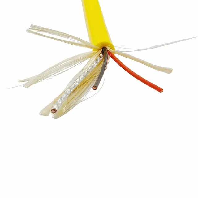
PDK81601 zero-buoyancy optoelectric umbilical with 2×4 mm² power cores and six single-mode fibres, 9 t tensile strength, foamed PUR sheath, 25.5 mm OD.
Product overview
Zero-buoyancy cables are a class of special cables whose overall finished density approaches that of water, so that they are approximately neutrally buoyant underwater. Ordinary underwater cables sink to the seabed under their own weight or ballast and rub against mud and sand over time, whereas a zero-buoyancy construction uses a balanced ratio of foamed sheath and high-strength fibre to let the cable float at its working depth, reducing disturbance to the vehicle's attitude, lowering drag and preventing damage from the cable dropping under its own weight. Such cables are mainly used on remotely operated vehicles, underwater robots, underwater camera and lighting units, buoys and various underwater observation and work platforms, carrying power supply, control signals and data transmission.
The optoelectric model PDK81601-2×4mm²+6SMF-9t in this series integrates larger power cores and multi-core single-mode fibre in one cable body, so that a single installation provides both power and data return and the number of underwater joints is reduced. The cable is built around the power cores and single-mode fibres, with high-strength fibre in the filler and wrapping layers carrying the mechanical load and a foamed sheath on the outside; overall tensile capacity reaches the tonne range and the finished outer diameter is controlled to specification, making it suitable for operation with a deployment winch.
Construction
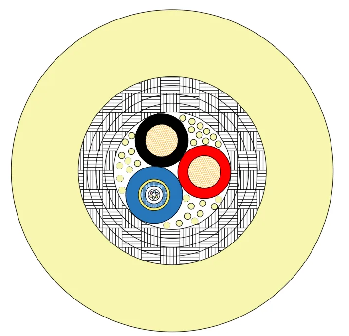
- Conductor: bare copper, multi-filament stranded, stranded diameter approximately 2.6 mm.
- Insulation: polypropylene, average thickness 0.8 mm, minimum thickness not less than 0.68 mm, insulation diameter approximately 4.2 mm, identified by black and red.
- Fibre unit: six single-mode armoured fibres, fibre unit outer diameter approximately 4.5 mm.
- Fillers: 30 high-strength liquid crystal polymer fibres, combining tensile capacity with core roundness.
- Wrapping: four wrapping layers formed from multi-strand fibre bundles.
- Outer sheath: foamed thermoplastic polyurethane, yellow, average thickness 5.3 mm, minimum thickness 4.5 mm.
- Finished outer diameter: 25.5 mm, tolerance ±1 mm.
The conductor is multi-strand bare copper, balancing flexibility and current-carrying capacity; the polypropylene insulation maintains stable dielectric strength at thin wall thickness; the single-mode armoured fibre unit withstands bending and lateral pressure during installation and repeated deployment; the outer sheath of foamed thermoplastic polyurethane lowers the cable density towards that of water on the one hand, and on the other provides an outer layer resistant to abrasion, hydrolysis and UV. The filler and wrapping layers use high-strength fibre bundles to transfer tensile loads generated during deployment away from the conductors and fibres, which is the key to a subsea tether surviving repeated spooling without damage to the transmission units.
Key characteristics
- Neutrally buoyant: overall cable density approaches that of water, giving approximately zero buoyancy underwater and making it easier for a vehicle to hover and manoeuvre.
- High tensile strength: the pulling capacity of the cable is shared by the high-strength fibre fillers and the multiple wrapping layers, matching operation with a deployment winch.
- Wide temperature range: the combination of insulation and sheath materials covers a broad span from low to relatively high temperatures, suiting different waters and seasons.
- Bending performance: the minimum bending radius is defined as a multiple of the cable diameter, allowing repeated spooling on winches and guide mechanisms.
- Depth capability: designed for a relatively high water pressure rating, and the construction can be adjusted further to the actual working depth.
- Integrated power and fibre: power and single-mode fibre are installed in one cable, reducing underwater connection points and the probability of system failure.
Electrical and optical performance
- Rated voltage: 0.6/1 kV.
- Maximum DC conductor resistance (20 °C): approximately 4.64 Ω/km for the 4 mm² power cores.
- Fibre type: single-mode G657A2, fibre unit in an armoured construction.
- Fibre attenuation: no more than 0.5 dB/km at 1310 nm; no more than 0.3 dB/km at 1550 nm.
- Rated temperature: -40 °C to +105 °C.
- Minimum bending radius: 20-25D (D is the cable diameter).
- Rated tensile strength: 9 t.
- Transverse underwater depth rating: 2 MPa, adjustable to the actual working depth.
The DC resistance values above are given at a common reference temperature, and the conductor DC resistance data for the other models in the series follow the same basis; they meet the power supply and medium-distance power transmission needs of conventional underwater equipment. The attenuation figures of the single-mode fibre support the return of video, sensor and communication data, and the armoured construction of the fibre unit gives the fibre core additional protection during deployment and bending. It should be noted that when fibre and power cores share a cable, the design has to balance roundness, tensile load sharing and bending performance, so the outer diameter of such cables is usually determined jointly by the arrangement of the fibre unit and the quantity of fibre layers.
Related specifications in the series
The PAIDE Cable zero-buoyancy series covers a number of specifications defined by sheath layers, core combinations and tensile grades. The PDK81602 and PDK81301 specifications share a rated voltage of 300/500 V, and their signal cores and pairs also take the same maximum DC conductor resistance value (84.1 Ω/km). The following specification data for some models is provided to assist selection by application:
- PDK81602-2×20AWG+2×2×24AWG-200KG: a combination of 20AWG and 24AWG cores, foamed thermoplastic polyurethane inner sheath and thermoplastic polyurethane outer sheath, finished outer diameter approximately 10 mm, rated voltage and signal core DC resistance as the common values above, minimum bending radius 10D, tensile strength 2000 N, transverse underwater depth rating 5 MPa, and maximum DC conductor resistance of the large power cores 37.4 Ω/km.
- PDK81601-4×14AWG+2×2×24AWG AS-200KG: 14AWG and 24AWG bare copper conductors, polyethylene insulation, aluminium foil shield over the pairs, cotton yarn and aramid fibre fillers, foamed polyurethane outer sheath in yellow, finished outer diameter 16.5 mm, rated voltage 450/750 V, minimum bending radius 15D, maximum DC conductor resistance 8.8 Ω/km and 89.2 Ω/km respectively.
- PDK81601-1×2×26awg-150KG: a single-pair construction with a conductor stranded from seven filaments, polyethylene insulation, aramid fibre fillers, foamed polyurethane sheath, finished outer diameter approximately 4 mm, rated voltage 300/300 V, minimum bending radius as the 14AWG specification above, maximum DC conductor resistance 146 Ω/km, suitable as a small-section signal channel.
- PDK81301-3×(2×0.22mm²+D 0.35mm²)AS+2×0.96mm²+1×0.14mm²-530KG: contains shielded pairs with drain wire and aluminium foil, two power cores of about 1 mm² and one auxiliary core, filled with high-strength fibre together with water-blocking yarn and a potted construction, an outer aramid braid reinforcement layer, foamed thermoplastic polyurethane outer sheath in orange, finished outer diameter 12.2 mm, rated voltage and pair DC resistance as the common values above, tensile strength above 5300 N, and maximum DC conductor resistance of 19.4 Ω/km and 131.2 Ω/km for the two power and auxiliary cores respectively.
The models above fall into single-layer and double-layer sheath types: the double-layer construction uses foamed material as the inner sheath to form the buoyancy layer and polyurethane as the outer sheath for abrasion and hydrolysis resistance; the tensile grade is set by the specification and quantity of aramid or high-strength fibre and covers the usual range from tens of kilograms to several tonnes. In selection, the fibre layer can first be defined by the tensile requirement, then the core combination by the number of power and signal channels, and finally the outer diameter and buoyancy state checked against the application requirements.
Typical applications
- Remotely operated vehicles: as a zero-buoyancy tether carrying power, control and video signals while reducing the cable's restraint on vehicle movement.
- Underwater robots and work tools: power and signal channels for inspection, cleaning and cutting equipment.
- Underwater camera and lighting: power for cameras and fill lights, with high-definition video returned over fibre.
- Buoys and underwater observation platforms: hydrolysis- and UV-resistant connection channels for long-term deployment.
- Towing and deployment systems: repeated spooling on winches, with the fibre reinforcement carrying the tensile load.
Customisation and selection notes
Selecting a zero-buoyancy cable usually requires several conditions to be defined: working depth and the required buoyancy state, supply voltage and load current, the number and type of fibres required, the permissible finished outer diameter and weight per metre, the deployment method and the allowable minimum bending radius, and the required tensile strength. On this basis the core and cross-section combination, shielding method, sheath material and colour, print marking and length marking can be adjusted; for parameters not yet fixed, a proposal can be provided according to the actual conditions. The parameters above are taken from the corresponding PAIDE Cable specifications, and supply is subject to the confirmed specification. If an existing model does not fully match the requirement, customisation support is available from PAIDE Cable.
Related in Zero-Buoyancy Cables
 Buoyant cable 3x0.75+STP CAT6
 Buoyant cable, single sheath, 1-core fibre, 200 kg tensile
 Double-layer neutrally buoyant cable 2×14AWG+24AWG+1SMF
 Double-layer zero-buoyancy 2×0.75 + (1×2×0.2)P
Engineering enquiry