TS 2×2.5mm²+2×1.0mm²+ATS 1×2×0.5mm² Watertight Optoelectric Cable
Watertight Optoelectric Cables · Marine & Subsea
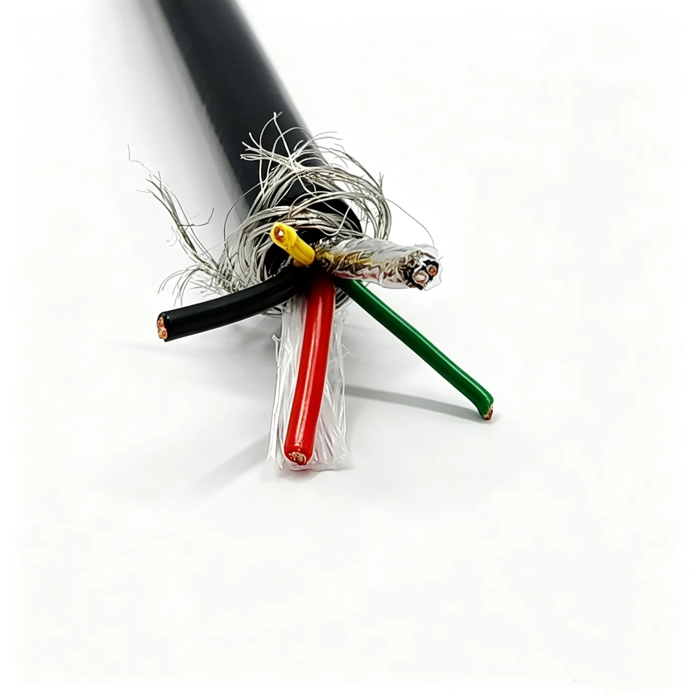
TS 2×2.5mm²+2×1.0mm²+ATS 1×2×0.5mm²
Watertight optoelectric cable with two power groups and one ATS data pair, bare copper, PE insulation, double sheath and braid armor, 13.2 mm.
Product overview
This watertight optoelectric cable uses a combined TS and ATS multi-group construction, concentrating power feed and data signal transmission in one cable body for equipment that works in water or wet environments for long periods. Compared with the separate cabling common on surface equipment, the composite cable reduces the number of harnesses and connectors, simplifies the launch and recovery mechanism and reduces the number of sealing points at penetrations, which suits duty where the cable is repeatedly run between winches, cable sheaves and seals.
From a design standpoint such a cable has to satisfy three things at once: the power group and the signal group must not interfere with each other; the cable must remain round in section with the groups tight after repeated coiling and bending; and the outermost layer must withstand continuous friction against structural parts and cable guide devices. The construction of this product is organized around these three points, with the power cores and data cores arranged as separate groups and shielding, fillers, tapes and armor built up layer by layer.
Construction and materials
- Conductor: stranded bare copper (2.5 mm²), stranded (1.0 mm²), stranded (0.5 mm²).
- Conductor stranded diameter: approximately 2.05 mm, 1.29 mm and 0.91 mm for the three cross-sections.
- Insulation: PE, 0.57 / 0.4 / 0.34 mm thick, giving insulation diameters of approximately 3.1 mm, 2.1 mm and 1.6 mm.
- Core sequence and colors: the two power groups use black, red and green, yellow insulation; the data pair is blue and white, so that both ends can be terminated by number.
- Data group: the blue and white cores are first twisted into a pair, then covered in turn with aluminum foil, a tinned copper braid and a polyester tape to form a continuous shield and tape construction.
- Cabling: the groups are stranded together, the interstices filled with clear PP yarn and the assembly bound with non-woven tape; the cabled diameter is about 7.4 mm.
- Inner protection: a tinned copper braid is applied over the core, stranded wire, 16 spindles, coverage about 80%; after non-woven tape wrapping a black TPU inner sheath 1.0 mm thick is extruded, giving a diameter of 9.8±0.3 mm at this layer.
- Outer armor: a further braid of 304 stainless steel wire, with the same wire specification and spindle count as the inner layer, forms a cut-resistant mechanical protection layer, followed by non-woven tape separation.
- Outer sheath: TPU, 1.5 mm thick, black, extruded, finished outer diameter 13.2±0.5 mm.
Key features
- Power and signal in one cable: a single installation provides both power and communication, reducing external harnesses and connectors and therefore the number of sealing points in the housing.
- Double-shielded data channel: the data pair uses aluminum foil plus tinned copper braid composite shielding fully covered by polyester tape, which helps suppress the effect of external electromagnetic interference on the signal.
- Double sheath and double armor: the inner sheath provides the insulation and water-blocking base, while the outer stainless steel braid takes the mechanical duties of abrasion, cut and tensile resistance; the two layers have clearly separated functions and suit routes with a risk of mechanical scraping.
- Construction stability: the core is filled with PP yarn and wrapped layer by layer with non-woven tape, so the cabled section is round and the groups do not shift or loosen after repeated coiling and uncoiling.
- Sheath adaptability: the TPU sheath is oil resistant, abrasion resistant, hydrolysis resistant and has some low-temperature flexibility, and keeps its surface intact in wet, immersed and oily environments.
- Handling reliability: the fillers and tapes limit relative slip between groups, so the sheath does not bulge during repeated handling and the shield and armor are not easily broken or displaced.
Electrical and mechanical performance
Rated voltage, long-term working temperature, minimum bending radius and permissible tensile load depend directly on working depth, installation method, handling frequency and end preparation, and must be determined for the specific conditions. The cable uses bare copper as the conductive body with PE insulation for a stable electrical basis, while the mechanical side is handled by the filler construction, non-woven tapes and the double metallic braid.
Typical applications
This construction suits subsea equipment that must provide power and data return along the same route. During installation the cable is driven by a winch or handling mechanism and enters a sealed housing at the end, so roundness, torsion resistance and sheath abrasion resistance are important, as is shield continuity.
- Power and signal return for subsea vehicles and various subsea work platforms;
- Power and data lines for subsea camera, lighting and sensor equipment;
- Cables for subsea winches and cable guide mechanisms requiring frequent handling;
- Composite connections between surface and subsea equipment;
- Mobile cable installations in wet, immersed or oily environments.
Selection and customization
- The number of groups and the cross-section combination can be adjusted to project needs, and the pairing of power and data cores can be rearranged;
- Shielding can be aluminum foil, braid or a composite; the number of armor layers and the material can be set by the mechanical protection level required;
- Sheath color, diameter tolerance and reel length can be set to the requirements of the handling equipment and the penetration;
- End preparation and sealing should be considered together with the overall cable arrangement to avoid damaging the shield and armor during on-site assembly.
The above is a general construction description; specific parameters, test items and acceptance methods are subject to the specification document confirmed by both parties.
Related in Watertight Optoelectric Cables
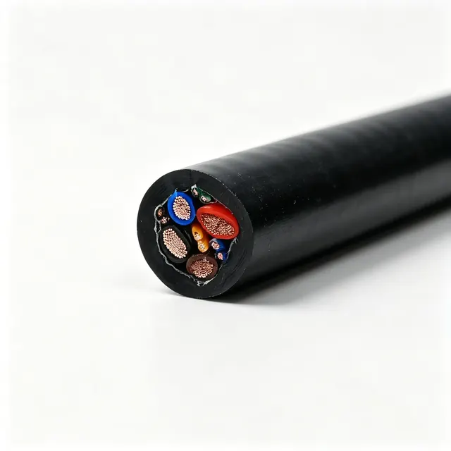 4×2×24AWG (UTP) + 2×14AWG + 2×12AWG
 Custom
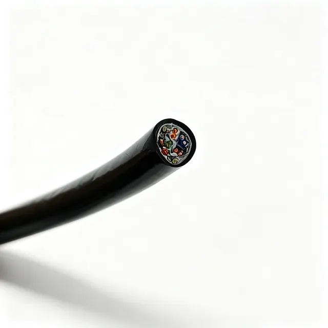 Longitudinally watertight cable 2×22AWG+STPCAT6-100KG
 PDK81301
Engineering enquiry